
| Knowledge of RF Circulators |
|
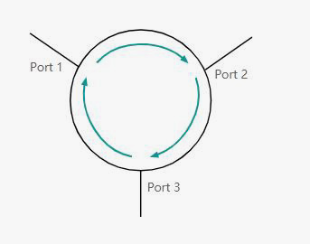
RF or microwave circulators or isolators are devices that typically have three and sometimes four ports, and they are used in RF system designs that need to transmit power from one port to another while isolating the power from the other port. RF circulators are used as diplexers in many RF applications, allowing both transmit and receive functions to be performed simultaneously, and they are widely used in RF design applications, including radar systems and various professional radio communication systems. RF circulators get their name because they transmit power from one port to another, for example, cycling from port 1 in to port 2 out and from port 2 in to port 3. Working Principle of RF Circulator Connections to RF circulators are often called ports, otherwise they are usually numbered 1, 2, 3, etc. The RF circulator gets its name because it only cycles the power that enters one port to the next. The signal applied to port 1 will be passed to port 2: The signal input to port 2 will be passed to port 3, but will not be returned to port 1. The input from port 3 is passed to port 1, but not back to port 2.
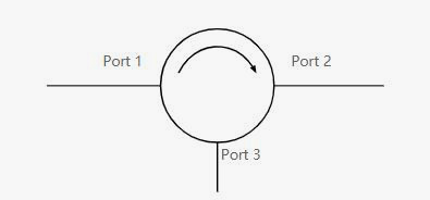
An ideal circulator would transfer all power from one port to the desired port and not to any other port. But in reality, there will always be some attenuation in the transmission path, and some signal will always leak to the port that should be isolated. The key RF circuit design challenge for these devices is to ensure that optimal transmission and isolation occurs. Circulators may use strip-line printed circuit board technology (but usually use very low loss dielectric or PCB materials) and are contained in metal boxes with connectors or other connections to the outside world - some even use surface mount technology. Other circulators may be based on waveguides, and these circulators can be used in RF system design applications incorporating waveguide technology. The type of interface and technology required for any given instance will depend on the RF circuit design applied. In terms of their operation, most RF circulators are based on the use of ferromagnetic materials. There are two main types: Three-port Circulators: Three-port "Y-junction" circulators are based on eliminating waves that travel through two different paths near magnetized materials. Circulators can be either type, while more compact devices based on strip lines are 3-port types. Four-port circulators: A four-port circulator based on Faraday rotation of waves propagating in magnetized materials. Using this technology, they were able to route the RF signal to four ports. RF Circulator Circuit Symbol In addition to other electronic components, the RF circulator has its own circuit symbol, which is used to represent it on an electronic circuit diagram or schematic diagram. The basic symbol consists of a circle and an arrow indicating the direction of the power cycle. Usually ports are shown in clockwise order around a circle: port 1, port 2, and finally port 3.
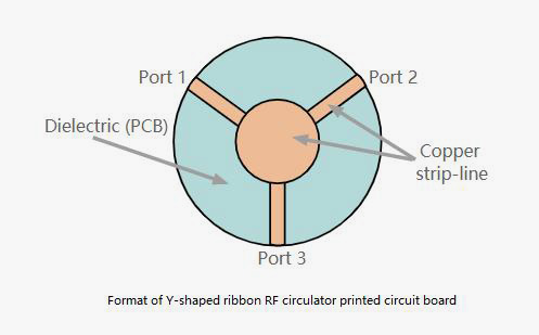
It is worth noting that each port, whether a coaxial feeder or a waveguide, appears as a single wire rather than a pair of conductors. One common form of RF circulator is formed by a Y-shaped portion of a microstrip or strip line transmission line located on a printed circuit board or other dielectric. The ports are placed 120° apart, so they are equidistant around a circle.
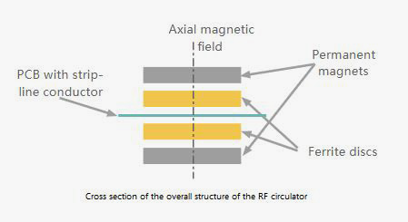
The printed circuit board assembly is sandwiched between two pieces of ferrite, and then on the outside of it, two strong magnets are held in place. The assembly builds a strong magnetic field through the ferrite disk in the axial direction, which concentrates the magnetic field around the Y junction, known as bias.
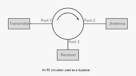
When a signal is applied to one of the ports, an electromagnetic field is generated in the strip line, which interacts with the magnetic field from the magnet, and there is a complex interaction between them. This results in the signal only being transmitted around the circulator to the next port. The circulator assembly consisting of a Y junction and a ferrite disk has a distinct resonant frequency - the assembly actually forms a resonator. For obvious reasons, circulators do not operate at this frequency, but above or below it, because the insertion loss, i.e. attenuation, is much lower. RF Circulator Application RF circulators have many applications in various RF circuit design applications. Usually they tend to be used at microwave frequencies, so they are often referred to as microwave circulators. One of the most obvious and common applications of RF circulators is in radar systems or radio communication systems, where the transmitter and receiver use a common antenna.
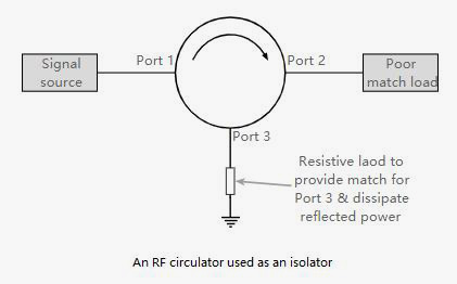
For example, the transmitter output is connected to port 1, the antenna is connected to port 2, and the receiver is connected to port 3. Therefore, the transmitter power will be cycled to the antenna, not the receiver, and the signal received by the antenna will be cycled to the receiver. In this way, the receiver is isolated from the transmitter, but the antenna has a power source from the transmitter and passes the received signal to the receiver without any mechanical switching. RF isolators: RF circulators can be used as RF isolators. These are useful for protecting transmitter output amplifiers that must operate at high VSWR levels. If connected directly to an antenna in these cases, the power amplifier may be subjected to high voltage or current levels, so the amplifier may be damaged by them. Often transmitters need to operate over very wide bandwidths, in these cases it is not possible to maintain a good impedance match over the entire bandwidth, and destructive levels of VSWR may be seen. To overcome this problem, circulators can be used to protect PA from reflected power. To do this, the transmitter is connected to port 1 and the antenna is connected to port 2. Port 3 is usually connected to a 50Ω load - this is required because the isolation level depends on a good impedance match presented on the different ports. If there is a poor match or an open circuit, isolation performance will be compromised.
The transmitted power is transferred from port 1 to port 2 and transmitted to the antenna. Any reflected power will be returned along the feeder and passed from port 2 to port 3, where it can be dissipated in the load. In this way, the RF power amplifier will be able to operate at a high feeder VSWR, but protected by a circulator that acts as an RF isolator. The load on port 3 needs to provide a matched impedance: The isolator needs to match an impedance on the port to maintain a level of isolation from that port. Rf circulators and isolators are widely used in many microwave and other RF circuit design applications. From radio communication equipment to radar, and many other applications. The fact that they transmit power from one port to another specific port only enables them to be used as duplexers, thus allowing both the transmitter and receiver to operate on nearby frequencies at the same time, and enabling RF power amplifiers to operate under load with poorly matched impedance.
|
Product Categories
RF Isolators
RF Circulators
Coaxial Fixed Attenuators
Coaxial Fixed Terminations
High Power RF Attenuators
High Power RF Resistors
High Power RF Terminations
Feed Through Capacitors
RF Power Dividers
RF Filters
Contact Us
No.981, Baozhou Road,Quanzhou 362000, Fujian, China
Phone: +86-595-22597735
Fax: +86-595-22557059
E-mail: sales@ketemicro.com
support@ketemicro.com (technical support)


Copyright © 2020 Kete Microwave Electronics Co.,Ltd. All Rights Reserved.