
| Know More about Coaxial Attenuators |
| Date: 2023-11-01 View: 311 |
|
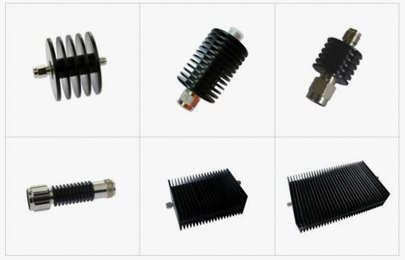
A coaxial attenuator is an energy-losing RF/microwave component that contains a resistive material. The Attenuators are widely used in various situations where power level adjustment is required. The basic material of coaxial attenuator is resistive material. The usual resistance is a basic form of coaxial attenuator, and the resulting resistance attenuator network is a lumped parameter attenuator. The corresponding frequency attenuator is formed by placing the resistance material into the RF/microwave circuit structure of different bands through a certain process. If it is a high-power attenuator, the volume must be increased, and the key is the heat dissipation design. The technical specifications of coaxial attenuator include the operating frequency band, attenuation amount, power capacity, return loss and so on. 1.The Working Frequency Band: the working frequency band of the attenuator refers to the use of the attenuator in the given frequency range, the attenuator can reach the index value. Since the RF/microwave structure is related to frequency, components in different frequency bands have different structures and cannot be universal. The working frequency band of modern coaxial structure attenuators is quite wide, which should be paid attention to in design or use. 2. Power Capacity: attenuator is an energy consumption element, power consumption into heat. It can be imagined that after the material structure is determined, the power capacity of the attenuator is determined. If the attenuator is subjected to more power than this limit value, the attenuator will be burned. When designing and using, the power capacity must be defined. 3. Attenuation Amount: Regardless of the mechanism and specific structure of the formation of power attenuation, the attenuator can always be described by a two-port network. The input power of the signal is P1, and the output power is P2, and the power attenuation of the attenuator is A (dB). If P1 and P2 are expressed in decibels milliwatts (dBm), the relationship between the power at both ends is P2 (dBm) = P1 (dBm) -A (dB) It can be seen that the attenuation describes the degree to which the power becomes smaller after passing through the attenuator. The amount of attenuation is determined by the material and structure of the attenuator. The attenuation is measured in decibels, which is convenient for calculating the index of the whole machine. 4.Return Loss: return loss is the standing wave ratio of the attenuator, requiring that the input-output standing wave ratio at both ends of the attenuator should be as small as possible. We want the attenuator to be a power consuming component that cannot affect both ends of the circuit, that is, it is matched with both ends of the circuit. This factor should be taken into account when designing attenuators.
|
Product Categories
RF Isolators
RF Circulators
Coaxial Fixed Attenuators
Coaxial Fixed Terminations
High Power RF Attenuators
High Power RF Resistors
High Power RF Terminations
Feed Through Capacitors
RF Power Dividers
RF Filters
Contact Us
No.981, Baozhou Road,Quanzhou 362000, Fujian, China
Phone: +86-595-22597735
Fax: +86-595-22557059
E-mail: sales@ketemicro.com
support@ketemicro.com (technical support)


Copyright © 2020 Kete Microwave Electronics Co.,Ltd. All Rights Reserved.